
Project Overview
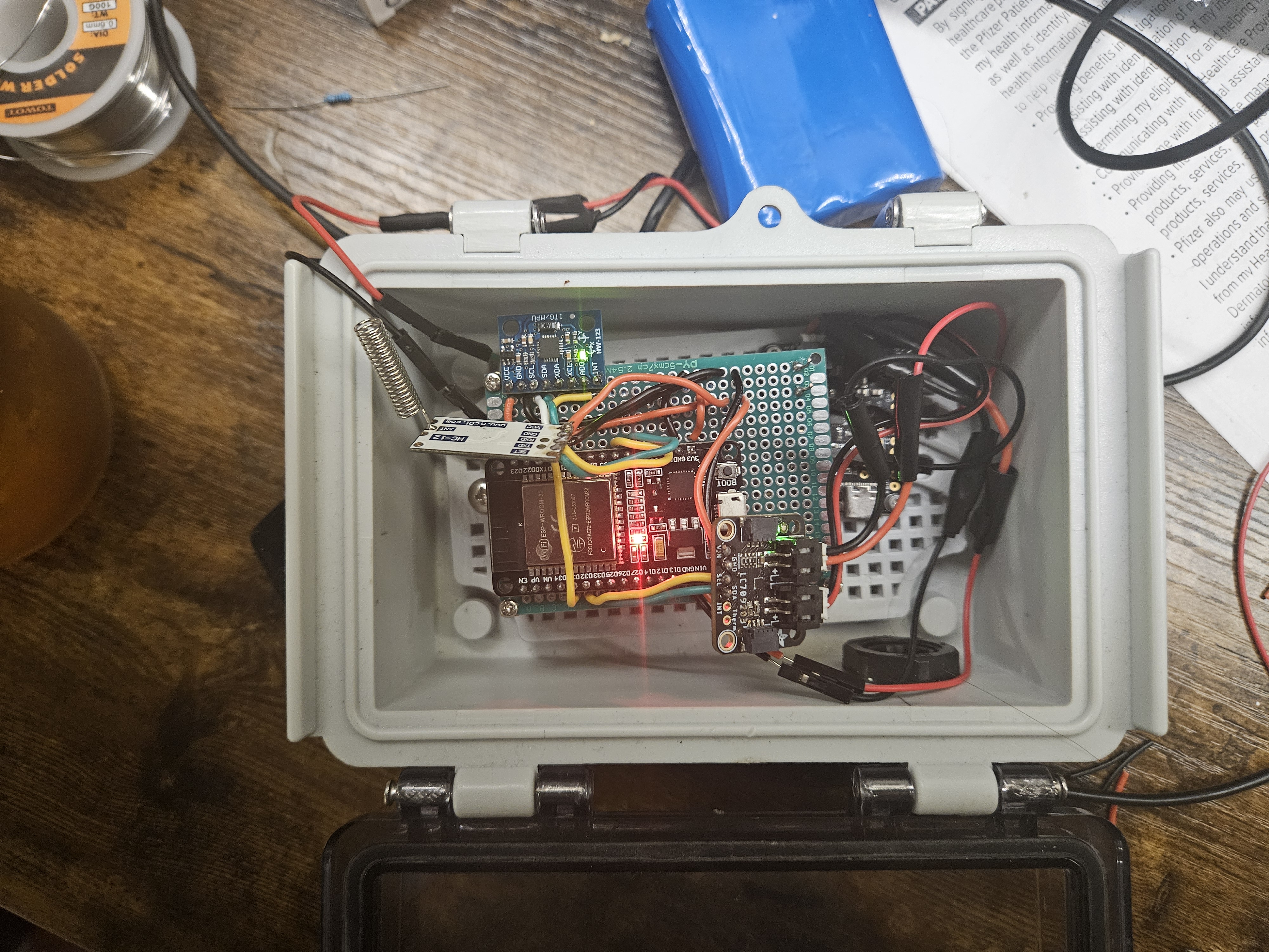
This project was borne from a lack of bump sensor products that would integrate with my phone or with Home Assistant. I wanted something to put on my motorcycle to know if the cover was lifted or if the motorcycle was bumped. A couple of iterations later, I settled on a transmitter of a ESP-WROOM-32 with code in C++ powered by a LiPo battery running with an MPU-6050, an HC-12, an LC709203F, a BQ24074 and optional solar panels. The ESP wakes up on an interrupt signal from the MPU or at an adjustable interval to take the battery voltage reading, and sends this data off to a receiver that runs on a Raspberry Pi Pico running a bit of microphython with an HC12 used to receive signals that uses WiFi to dispatch relevant MQTT messages to Home Assistant. I would like to take this a little further still and shrink the form factor by creating a PCB and using a SIM to have this bump sensor work anywhere I go, not just in the immediate vicinity of the receiver. Integrating GPS might be a great addition as well.
List of Materials
The minimum things you will need to get a bump sensor working are an MPU6050 and an ESP32. If you don't plan on using a battery with it, you don't need much else. For the version I built, you will need the following:
- ESP32: I used an ESP-WROOM-32 dev board since they're cheap. Amazon link
- Raspberry Pi Pico w: Used for the receiver. Amazon link
- MPU6050: Amazon has these for cheap. Amazon link
- HC-12: These are also low cost on Amazon, you'll need two. Amazon link
- LC709203F: Adafruit makes a ton of neat modules, and this is one of them. Adafruit link
- BQ24074: if you plan on either using solar panels or want an easy way to charge the battery, this is a good idea. Adafruit link
- LiPo battery: I used quite big batteries, but if you reduce your power consumption you should be fine with smaller batteries. Amazon link
- Solar panels: Used in combination with a BQ24074. Amazon link
- Buck converter/voltage booster: this is needed to power the esp32. Amazon link
- Enclosure: depending on how you plan to use this bump sensor, you may want a waterproof enclosure. Amazon link
- Typical other supplies: wiring, soldering iron, solder, prototyping circuit board, back off screws, etc
Wiring
Receiver
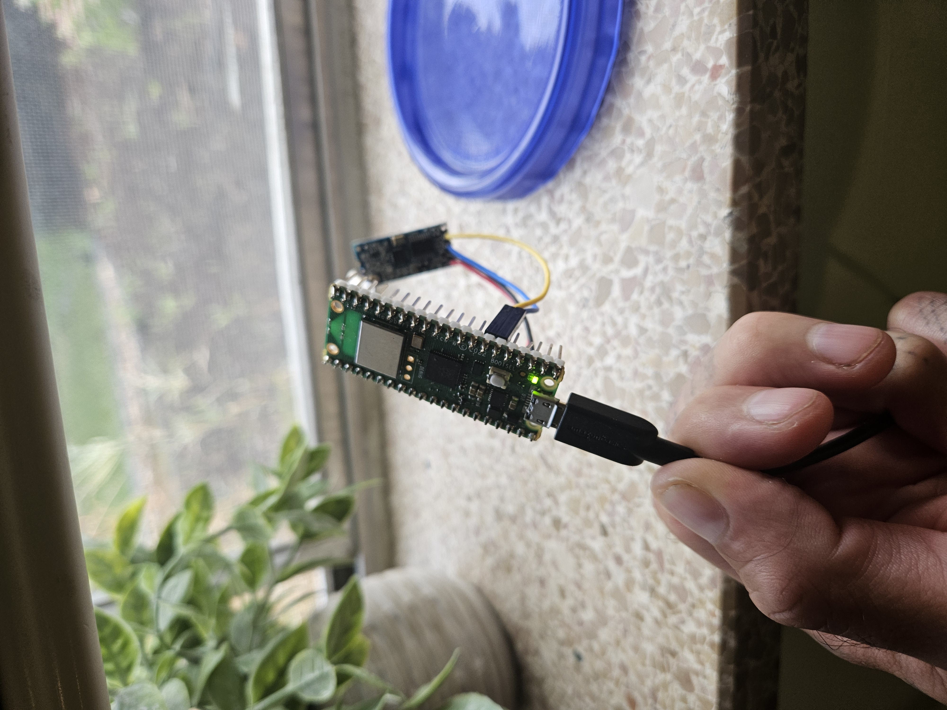
The Raspberry Pi Pico receiver is the easiest part to set up. You will need to solder the HC12 to some wires and connect the wires to the appropriate pins on the pico. Since the HC12 is the only peripheral, I didn't bother even soldering the HC12 directly to it and instead used female jumper cables to establish the connection to the right pins, then soldered those to the HC12. I wanted to be able to reuse the Pico (the better option would be to just solder pins to the HC12 and have female jumper cables connecting the two, so reuse of both is possible). The picture at the top shows of this blog post shows the Pico/HC12 wiring. The RX/TX pins are 5 and 4, respectively, and the VIN and GND should be connected to the Pico's 3.3V and GND pins.
Transmitter
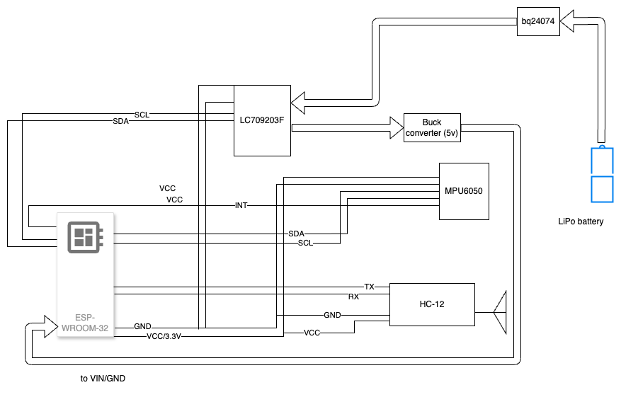
The wiring for the transmitter has a little more going on, but it still isn't all that complex.

The main components are the MPU and the HC-12, both wired to share the VCC 3.3V and GND connections. The LC709203F also shares this circuit. After that, the correct pins should be connected to their respective modules to communicate with the ESP32. The SCL and SDA pins on the MPU6050 should be connected to GPIO22 and GPIO21, respectively. The MPU's INT pin should be connected to GPIO35. On the HC12, the TX should be connected to the ESP32's GPIO16 and the HC12's RX should be connected to GPIO17 on the ESP32. For the LC709203F, the SCL on it should be wired to the GPIO32 on the ESP and SDA should be wired to GPIO33. Side note: the LC709203F and the MPU6050 should be able to exist on a single I2C bus, but since these were the only two peripherals connected using I2C, I just got lazy and connected them to separate sets of pins.
The battery should be connected to the BQ24074. There are labels on the silk screen that tell you which terminal is positive and which is negative (off brand batteries might have the polarity reversed, use your multimeter!). The "LOAD OUT" (printed on the silk screen) should lead to the LC709203F. These do not have a direction that the power needs to flow, so either JST connector can be used here. After that, the power needs to flow to the buck converter, which should be at 5v, and then to the VIN and GND pins of the ESP32. If you get the buck converter that has a potentiometer, use a multimeter with the battery hooked up to it to figure out where 5V is.
Interfacing Transmitter, Receiver and MQTT/Home Assistant
I will run through an explanation of the interactions between the components at a high level and talk about more specifics of the code. The overall flow of information goes like:
ESP32 sends signal via HC12 ->
Pico Receiver receives signal via HC12 ->
Pico Receiver decodes the signal and dispatches a payload to an MQTT topic ->
Payload is received on an MQTT server running on Home Assistant
The code can be found in the Github Repo.
The battery_gauge_test.ino was for testing the LC709203F and the I2C
connection. I went ahead and left it in there if anyone else has a little
trouble in the beginning, but you have to have a battery plugged into the
LC709203F in order to get the I2C address read by the ESP32 (which I later found
out). There are two sections of code (the bottom section is commented out), one
which sets up the LC709203F and the other tests the I2C address on the I2C
circuit.
The next file, central_receiver.py is for the Pico that does the receiving of
signals. There are probably a hundred better ways to build a low bitrate
signaling protocol (the code could also do with some cleaning up while we're at
it), but I threw it together on the fly. You will see a
dict
that holds information that determines how to interpret messages from the
transmitter and determine what to pass on in a payload to the MQTT server. Right
now, there is one base key of 1. The idea was to have other sensors that might
be utilizing the same receiver, so when there was another message that came in,
say from a weather sensor, 2 would be its domain and it would have
corresponding topics and messages. The shortcoming of this approach is obviously
that the transmitters need to know this dictionary's structure, but the nice
thing is that it simplifies and shortens the messages sent (it will look
something like: 1,A,b), which means more reliability and lower chances of
signal interference.
When I set up this whole system, I fully intended the Movement Detected/No
Movement signals and state to come from the transmitter and the receiver was
going to be stateless. However, once I started messing around with trying to put
the transmitter in deep sleep, it meant keeping state and coordinating from the
receiver or Home Assistant was tricky. When the transmitter is asleep, no reset
signals can be processed by it. I moved a poorly thought-out
coordination of state into the receiver. As you can see
here,
there is a cmd_topic dict that has an MQTT topic that serves as a way for Home
Assistant to tell the receiver to do something. The topics in that dict are
registered to listen to and these
lines
show where, upon reception of a message on any cmd topic, the corresponding key
for that topic is immediately dispatched to my Home Assistant MQTT server. I
admit, it isn't the best way to do this; I think doing away with this pattern
altogether and simply housing state in whatever end system you use to display
the results of the motion transmitter is the right move. Simply let the
transmitter serve as a push provider. Future iterations will have this worked
out.
The motion_transmitter.ino file contains all the code for the ESP32
transmitter. This looks pretty different from the Pico transmitter code (in
movement_transmitter.py) because there is no comparison from the last reading
going on. It uses the INT signal going low from the MPU upon movement to send
data to the receiver. Every three hours (change the number of seconds
here
if you would like a different interval) the battery percentage is read and sent.
The movement_transmitter.py contains the micropython code that ran the first
iteration of the transmitter. It ran similarly to the ESP32 version except the
pico was awoken every 3 seconds from lightsleep and readings from the
LC709203F and MPU6050 were taken. This was way less efficient for the battery.
Addtionally, the movement type is also transmitted ("Pitch" or "Acceleration").
Right now, I have the battery percentage, the motion sensor state, and the
motion sensor receiver status as sensors in Home Assistant. The motion sensor
movement type was also used at one point, but since moving everything to the
ESP32, that part is unneeded now (I still included it in the yaml files in case
you want it). The yaml code that sets everything up is included in the
/home_assistant directory in the GitHub repo.
Wrap Up
Here is a video of the final result. Turn your sound up to hear the announcement that I get through my Sonos speaker:
This, like other projects I have done, not only fulfilled an actual need I had (knowing if someone was messing with my motorcycle) but also was a great learning experience. I got to learn more about using an interrupt signal to wake up an ESP32, good strategies for battery efficiency (ESP32s will now be my go-to microcontroller for battery-operated projects because of their deep sleep wakeup functionality), and how to communicate over distances if WiFi isn't an option. On the communication over distances note, there was something I discovered well after I was into the building phase of this project that would have helped me out: ESP-NOW. This will be a future consideration for similar projects as it is a robust solution that I wouldn't have to build from scratch like I did with the HC12s, transmitter/receiver and custom code approach.
As with any project, I am already thinking of ways I could do things better and would like to be able to use this even if I am out of range of the receiver, so I am going to create a version with the Lilygo T-SIM7000G board. This will let me utilize a cell network and free me from the chains of needing to be in same general area to know if someone bumped my motorcycle. The added benefit is that I will be able to use GPS, too! I am really excited to give this a shot.
If you have any questions about any part of this project, feel free to get in touch with me via the social media accounts I have posted around this website.
